description
- Detonation barrier
- Typ F.4.7000.20-IIC ( Hastelloy-characteristic with marking groove)
- Typ F.4.7000.40-IIC ( stainless steel)
Content
- description
- EG- certificate
- technical data
- special conditions
- service
- warranty
- description
- The detonation barrier F.4.7000.20 (40)-IIC (Ex-classification Ex IIG IIC) avoids the breakthrough of the flames in case of instable detonations and deflagration
- of combustable gas or gas/steam mixtures classified by explosion category IIC.
The detonation barrier consists of the mean components pressure proof housing, connector for the tubes and ceramic material (max. porousity: 80µm for
prevention of flame puncture.
The detonation barrier can be heated max. 200°C and the max. pressure is 3 bar (abs.)
- Certificate
EG- certificate: IBExU 00 ATEX 2058X
IBExU 00 ATEX 2059X
based on Standard DIN EN 1127-1:2008
EN ISO 16852:20107
- Technical data
length: 83,5 mm
diameter: 32 mm
thread: M 30 x 1,5; 30 lengh
gas connector: G 1/4“
max. pressure: 3 bar (abs.)
max. temperature: 200°C
mounting orientation user defined
flow direction user defined
material: stainless steel 1.4571; optionally hastelloy
resistance against flame transmission of H2/Cl2 mixture only hastelloy arrester
Ex-classification: IIC
Special admission H2-CL2 -mixtures up to 60°C only IBExU ATEX 2058X Hastelloy
- special conditions
The application of the detonation barrier is only granted for such gases whereby the .materials are resistant.
The application of the detonation barrier is restricted for Tubes max. 12 mm diameter.
The load limit for the fitting of the flame resistor is 80Nm
- service
The visual inspection of the detonation barrier is stipulated regularly.
If there are any corrosive influences the user must replace the barrier.
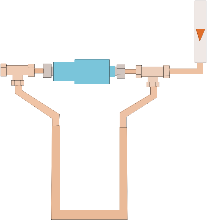
The measurement of the flow resistance (picture 1) is an suitable method to check the barrier.
Each detonation barrier enclosed a data sheet including the pressure Δp for different flow rates.
The condition of the barrier is easy to control by comparing the data.

- detonation barrier
- gas in
3 T- connector
4 U- Rohr- Manometer (1m)pressure sensor
5 flow meter 0...2 l/min
Pic. 1: schematic structure of the test installation
- WARRENTY