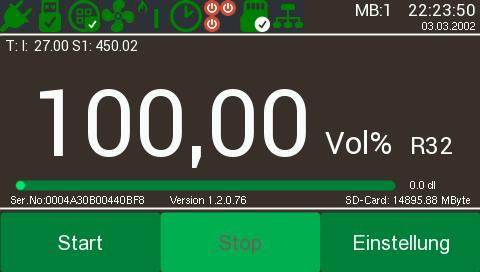
main display
please note
the shown oprating elements are possible and not all used for several applications.
The elements will be different to your MGA analyser.
The color can be coosed in the setup-mode (see chapter)

top line
• |
01.Symbol: power source while using accumulator here the nattery charge condition is shown |
• |
02.Symbol: USB-connection, empty USB-Symbol=no USB-connection, filled Symbol=USB-cable connected, filled Symbol and hook =Windowsoftware activ |
• |
03.Symbol: status of the sensor maybe "warmup" or "fault" can be shown |
|
• |
04.Symbol: meas gas pump,if pump is active this symbol is shown else not colored but grey |
|
• |
05.Symbol: display forming gas or inert gas (option) only used in combination to oxygen trace measurement |
|
• |
07.Symbol: Timersymbol, if active |
|
• |
08.Symbol: display if relais are built in. |
|
• |
09.Symbol: status symbol if SD-memory card is built in, |
|
• |
10.Symbol: Modbus activ |
• |
displays choosed measuring range if several ranges are activ |
• |
display date and time (not available in low-cost version). |
second and third line
• |
internal analyser temperature |
• |
sebsortemperatur, depending of the number of sensors up to 4 displays are possible. |
• |
internal air pressure - only available if the related sensor is built in. |
• |
measuring range , brelated to the end vaue of the 4... 20 mA range |
display measuring value
in the middle of the mean display - more than one value is possible .
forth line
• |
serial number |
• |
aoftware version number |
• |
free memory of the -maybe- built in SD card |
bottom line
• |
Button für start record - only active if SD memory is built in |
• |
Button für end record - only active if SD memory is built in |
• |
Button start adjustments |